
A linear flexible body in Adams Solver is usually a Craig-Bampton reduction of a finite element model: a few hundred shapes that stand in for tens of thousands of nodes. Done well, it moves, bends and vibrates like the full model. Done badly, it still runs, and nothing in the animation says it is wrong. These are the checks we run on every flexible body, shown on the e-drive housing from our solver settings test.
The part
- The housing. A generic cast-aluminum e-drive housing, an 11.0 x 5.9 x 8.7 in box with 0.31 in walls (14.2 x 6.5 x 8.7 in over the mount lugs and bearing bosses), 12.8 lb.
- Seven connection points. Four bearing seats and three mounts, each tied to the surface around it by a rigid link.
- The reduction. The full model has 67,452 nodes; the linear flexible body keeps 242 modes.
The six checks
| Check | Pass mark | The housing |
|---|---|---|
| 1. Mode count | 6 per connection point, plus the vibration modes asked for | 7 x 6 + 200 = 242 |
| 2. Rigid-body modes | Exactly 6, at 0 Hz | 6 at 0 Hz |
| 3. Clean modes | Orthogonal and scaled to unit mass | To about 5 parts in 100 trillion |
| 4. Statics against the full model | Within 0.1 percent; it should be exact | To 3 parts in 100 million |
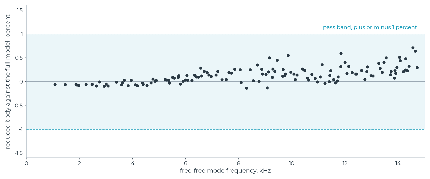
| 5. Free-free frequencies against the full model | Within 1 percent across the band that matters | 136 modes below 15 kHz, worst 0.71 percent |
| 6. The same static case in Adams Solver | Within 1 percent, same mass | 0.02 percent off; 12.82 lb in both |
Check 4 should be exact, and that is the point. A Craig-Bampton basis contains the static shape of every connection point by construction, so for loads and supports at the connection points a static miss is never reduction error. It is bookkeeping: node numbers, units, a coordinate frame. Check 5 is the one that tells you whether you kept enough modes.
How to read the chart: each dot is one of the housing's vibration modes with the part floating free, attached to nothing (a free-free mode), from the first at 1.1 kHz to the 136th near 15 kHz. Its height is how far the reduced flexible body puts that frequency from where the full model puts it, in percent. Inside the shaded band means within 1 percent. All 136 are inside, and the worst, 0.71 percent, sits near the top of the range, where a reduction is least exact. If the dots climbed out of the band toward the top, the body would need more modes.
Where the 242 modes come from
The reduction starts from two families of shapes: 200 vibration modes with every connection point held still, and 42 static shapes (7 connection points x 6 directions), one for each of the six ways a connection point can move (three moves, three turns) with every other connection direction held. Adams Solver needs shapes that do not couple through mass or stiffness, each with its own frequency, so it can set the six rigid-body shapes aside and damp every other mode on its own. The two families are combined and re-solved to get them. The result falls into four groups.
| Group | Count | Frequencies | What they are |
|---|---|---|---|
| Rigid-body | 6 | 0 Hz | The part moving as a whole |
| Elastic, checked | 136 | 1,074 Hz to 14.8 kHz | The part's real vibration modes (check 5) |
| Elastic, above the band | 76 | 14.8 to 20.7 kHz | The next modes up: less exact, still needed |
| Connection modes | 24 | 20.9 to 40.3 kHz | The local springiness of the bearing seats and mounts, written as very fast modes |
The connection modes look like vibration modes in Adams Solver, but they carry the local flexibility of the connections. Push on the input bearing seat with the mounts clamped: the modes up to 10 kHz carry only 52 percent of the deflection, and the 24 connection modes carry 33 percent. Switch them off and that seat comes out 1.5 times too stiff.
Do many or close connection points break it?
The common experience: a simple beam reduces cleanly and checks against a hand calculation, while a complex part with many connection points, or points close together, picks up error. We tested that directly on one steel plate, 11.8 x 3.9 x 0.31 in, with 2 to 20 bolt holes in a row, and with a close pair of holes whose ligament shrank from 2.76 in to 0.08 in.
- The reduction held every time. Statics matched the full model to 5 parts in 100 million or better in all ten cases, and every free-free mode came within 0.9 percent across the 10 kHz band.
- The connection flexibility moves to the top of the mode list. The highest mode climbed from 111 kHz with 2 holes to 355 kHz with 20, and to 288 kHz for the closest pair. With a 0.08 in ligament, the modes up to 100 kHz hold only 1.5 percent of the flexibility between the pair. Cut the rest, as a frequency-based mode selection would, and that connection comes out about 67 times too stiff.
- The rigid links stiffen the part itself. Against the bare plate, they raised the first ten modes 1 percent on average with 2 holes and 16 percent with 20. The full model carries the same links, so no check against it can see this.
So the method does not break down. What changes as connection points multiply and crowd together is where the part's connection flexibility ends up: in a handful of very high modes that are easy to switch off, and that a frequency-based mode selection drops first. That, and the stiffening from the links themselves, is where most flexible-body surprises come from.
The rules we use
- Tie each connection point to a patch the size of the real contact (washer face, bearing seat, bushing sleeve), never a single node.
- Keep rigid patches to the real contact, and use an averaging link where the joint lets the hole deform. Never let two patches share nodes.
- Use only the connection points the model needs; each one adds six modes.
- Keep the vibration modes (connection points held) to about twice the highest frequency that matters.
- Run the six checks on every flexible body, and keep the numbers with it.
- In Adams Solver, keep every elastic mode on, the connection modes above all, set the modal damping yourself, and set the integrator for the highest frequency that matters, not the highest mode in the body.
The housing and the plate are generic parts made for this work. The full-model references are the same meshes solved directly, with a consistent mass; the reduced bodies carry a lumped mass. That difference, not the reduction, puts some modes just below the full model, since a reduction on its own can only raise frequencies. Solved in Adams Solver.