
DSIM Reference Study · Vehicles
Virtual durability of a welded trailing arm
Generic part and vehicle, built in-house; not client work.
A light-truck rear corner over speed humps, sharp bumps, chuck holes (sharp-edged potholes) and rough roads. Stress across the arm's surface and at every weld toe, life in miles, and three redesigns compared in the model.
The question
A light truck crosses speed humps, sharp bumps, chuck holes and rough roads. Where on a welded trailing arm does the stress go, and will the welds last 300,000 miles?
The welds set the life, and rough road does most of the damage.
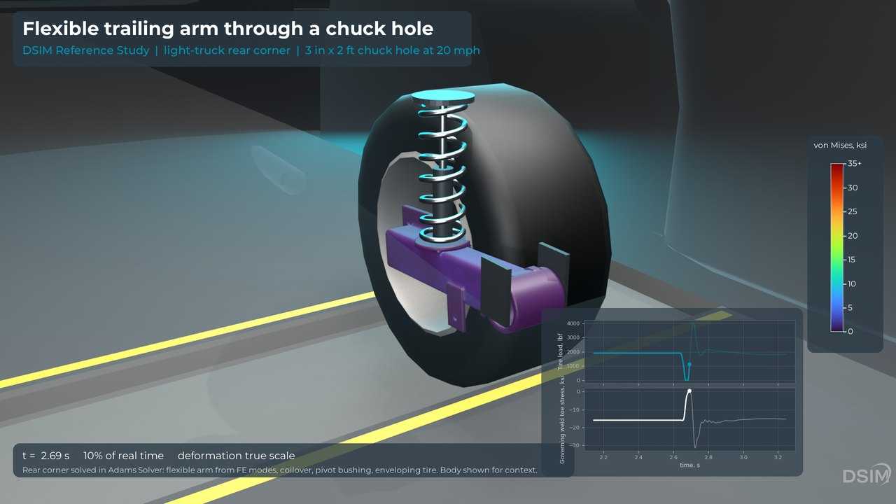
- Peak tire load: 2,550 lbf over the speed hump, 2,930 lbf over the sharp bump, 4,040 lbf in the 3 in chuck hole and 4,210 lbf in the 4 in hole, both at 20 mph.
- The governing weld is the front end of the wheel-mount plate fillet.
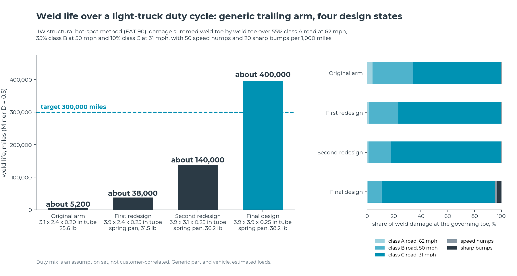
- 85 percent of the final design's weld damage comes from the 10 percent of miles on class C road, the roughest road in the duty; speed humps and sharp bumps add under 5 percent.
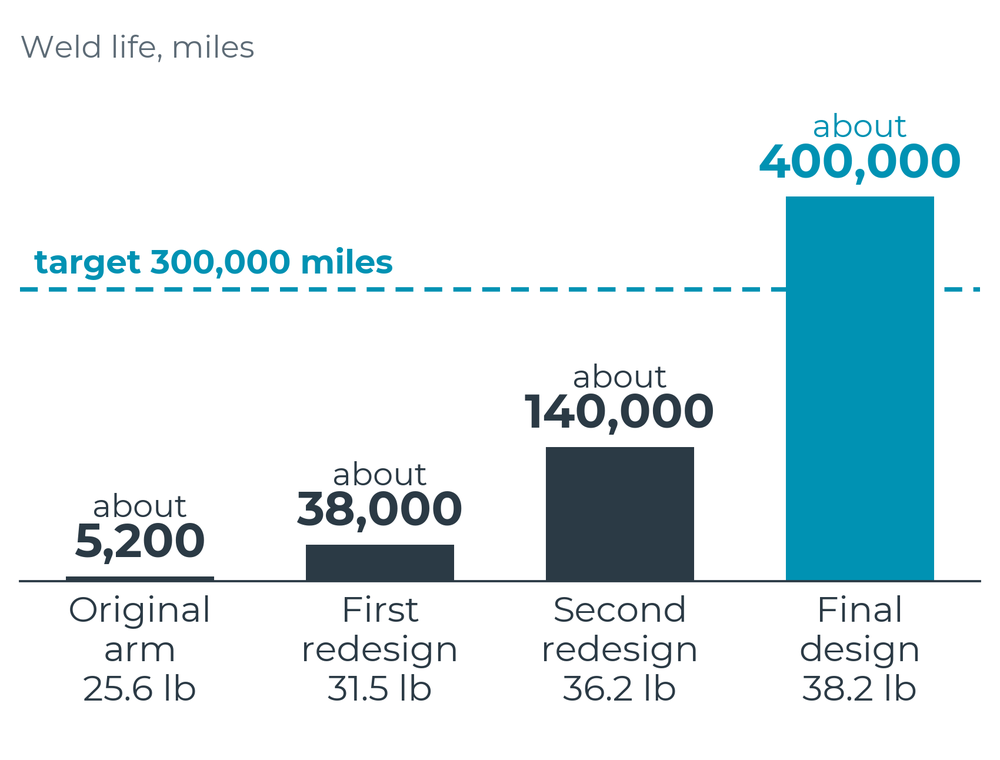
Weld life over an assumed road mix: four designs against a 300,000-mile target
| Design | Tube | Wheel-mount plate | Weight | Weld life | Against 300,000 miles (assumed duty) |
|---|---|---|---|---|---|
| Original arm | 3.1 x 2.4 x 0.20 in | 0.59 in | 25.6 lb | about 5,200 miles | 2 percent of the target |
| First redesign | 3.9 x 2.4 x 0.25 in, spring pan | 0.59 in | 31.5 lb | about 38,000 miles | 13 percent of the target |
| Second redesign | 3.9 x 3.1 x 0.25 in, spring pan | 0.59 in | 36.2 lb | about 140,000 miles | 46 percent of the target |
| Final design | 3.9 x 3.9 x 0.25 in, spring pan | 0.47 in | 38.2 lb | about 400,000 miles | 132 percent: meets the target |
Road profile inputs only, at constant speed: braking, acceleration and cornering loads are outside this study.
Methods
Model
- A multibody rear corner with a flexible trailing arm built from its finite element modes, a coil-over spring and damper, a pivot bushing and the wheel. The arm's modal damping is set explicitly to 1 percent; the solver default critically damps modes above 1 kHz.
- Tire: a single-point radial spring and damper on an enveloped road (a tandem-cam model checked against published tire measurements), with the fore-aft force from the road's effective slope. Radial stiffness and contact length are estimated; wheel spin and longitudinal tire slip are not modeled. A real program uses the client's tire model.
- Stress at every weld toe recovered every 0.1 ms. In the first round of runs (output every 2 ms), base-metal stress was also recovered at every surface node of the arm.
- Adams Solver with converged settings: GSTIFF SI2, an error tolerance 1,000 times tighter than the default, steps capped at 0.05 ms, output every 0.1 ms.
- Pivot bushing damping from a loss factor of 0.09, a published value measured on an automotive rubber bushing, applied in all six directions as viscous damping matched at the 45 Hz mode.
- Fatigue in the base metal (critical plane, rainflow, mean-stress correction) and at every weld toe (IIW structural hot-spot method).
Road events
- 3 in x 12 ft speed hump at 12 mph
- 3 in x 14 in sharp bump at 6 mph
- 3 in and 4 in x 2 ft chuck holes at 20 mph, and the 3 in hole at 10 mph
- ISO 8608 class A, B and C roads at 62, 50 and 31 mph
Assumptions, published so they can be judged
- Generic full-size body-on-frame SUV (a light truck) with 1,760 lb of sprung weight on the rear corner (about 1,900 lb at the tire, with the wheel, hub, brake and arm), 1.4 Hz ride, damping about 30 percent of critical, 245/75 R16 light-truck tire.
- S355 structural steel (about 51 ksi yield, comparable to ASTM A572 Grade 50). Fatigue properties estimated from the uniform material law; a real program replaces them with coupon data.
- Welds: IIW structural hot-spot stress from the fine-mesh read-out points on the standard mesh (the larger of the linear and quadratic extrapolations), FAT 90 design curve for load-carrying fillet welds, slope 3 to the knee at 10 million cycles and 5 below it with no cut-off, no mean-stress or thickness correction (as-welded, walls under 1 in). Miner sum 0.5, no partial safety factor; the final design clears the target by about 1.3 times on life.
- Only the rear corner is simulated (body heave). Road profile events at constant speed.
- Duty: 55 percent class A, 35 percent class B and 10 percent class C road, with 50 speed humps and 20 sharp bumps per 1,000 miles. An assumption set, not correlated to customer usage. Chuck holes were run on the second redesign as peak-load checks and are not counted in the duty: one 3 in strike at 20 mph does the weld damage of about 1.6 miles of the duty, so even 10 per 1,000 miles would shorten that design's life by under 2 percent. Each ISO road is one 820 ft random profile, and its damage per mile stands for that road's whole share of the miles.
- Pivot bushing damping is a published value, not a measurement of this bushing. Rough-road weld damage is sensitive to it, so a real program uses the supplier's bushing data.
How the chain was checked
The part and vehicle are generic, so there is no vehicle test to correlate against. On a client program the first check is against your measured loads or strain.
- Against measurement: the tire enveloping model against published measured step responses of a passenger-car tire, 8 of 8 cases, peak effective road slope within 0.9 degrees.
- Beam benchmark against hand calculations: deflection, first natural frequency, stress and fatigue damage within 0.65 percent.
- Weld hot-spot stresses from two independent finite element solvers: within 0.4 percent.
- Weld hot-spot stress with the mesh refined to the IIW fine-mesh rule, checked on the original arm: the highest-stressed toe, on a spring-seat weld the redesigns removed, rose 7 percent, and the wheel-mount plate weld, which sets every design's life, moved between 35 percent lower and 13 percent higher across its check points. Raw peak stresses change by up to 470 percent and are not used for weld life. The final design's plate weld was not refined; the published lives use the standard mesh.
- Vehicle model consistency: the static tire load equals the weight exactly.
- Rigid-arm route against the flexible arm: weld damage 0 to 12 percent low across the eight events.
- Solver convergence: tightening the error tolerance tenfold changes the class C weld damage by 0.02 percent.
- Weight study screen against the full simulation: within 3 percent on the four wide-tube designs run both ways, 10 to 13 percent high on the two narrow ones.
Further results
- Base metal: checked in the first round of runs on the original arm and the first two redesigns, over the five duty events on each and the three chuck holes on the second redesign: every stress cycle stayed below the steel's estimated endurance limit. It was not recomputed for the final design.
- Rough roads drive a 45 Hz fore-aft rocking of the wheel and arm on the pivot bushing. It took converged solver settings to see it, and it cut the weld life of every design run both ways by more than half. The tire here passes the road's fore-aft force straight to the wheel, with none of a real tire's fore-aft compliance or slip damping, so how strongly that mode is driven is the first thing to recheck with a client's tire model.
- Six candidate fixes were screened in 2 to 3 minutes each, then 108 designs (tube height, width and wall, and hub-plate thickness); the final design was run through the full simulation.
Every event was rerun with converged Adams Solver settings and a published bushing loss factor. The film above shows the 36.2 lb second redesign from the first round of runs; with the final settings its weld stress swings run 2 to 7 percent higher on the impacts and up to 20 percent higher on the rough roads.
Bring a part and the road it sees
On a client program, your own duty, tire model and bushing data replace the assumptions published here.
NDA-ready and US-based.