
We first gave this list as a webinar: the three biggest mistakes we see in Adams Solver models. Most of it held up; where it did not, we say so. We count down, as the webinar did.
Mistake 3: degrees in, radians inside
Adams Solver works in radians, always, so a motion meant as 10 deg/s but written as 10.0 runs at 10 rad/s: 57.3 times too fast. Write it as 10.0D or 10.0*DTOR. We drove a 1 lb rotor 4 in across for one second.
| Motion function as written | What the solver reads | Rotor after 1 s |
|---|---|---|
| 10.0 | 10 rad/s: 573 deg/s, 95.5 rpm | 573 deg, 1.6 turns |
| 10.0D or 10.0*DTOR | 0.1745 rad/s: 10 deg/s, 1.67 rpm | 10 deg |
| 10.0(deg), a unit label | A syntax error: the solver rejects the whole model | No run |
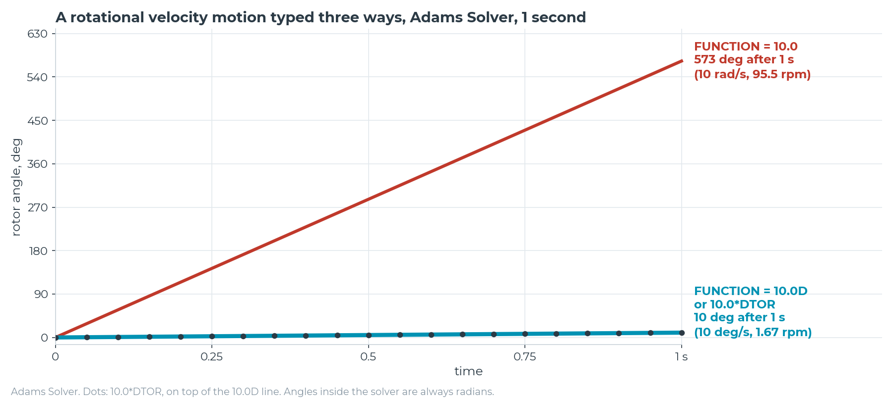
- Fields are converted, functions are not. With the modeling interface in degrees, an initial spin typed as 10.0 was written as 10D, but a motion function stayed 10.0. A design variable is the exception: one set to 10 deg/s went in as 10.0D.
- Unit labels in a function fail in the solver. 10.0(deg) drew only a warning while modeling and still went into the model file; the solver then refused the whole model.
The fix
- Write angles in functions with D or DTOR, and convert function results (requests, measures, variables) with RTOD.
- Keep unit labels out of functions; use a design variable.
- Check every driven motion once: run one second and read the angle.
Mistake 2: leaving the solver settings at default
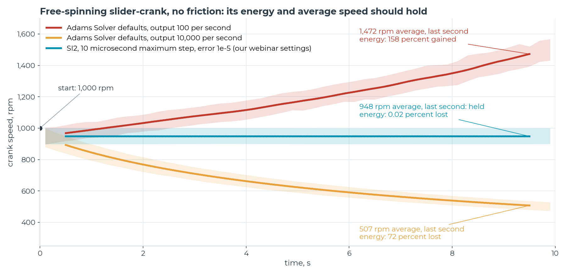
Left at default, the solver settings can make a frictionless mechanism speed up or slow down; in our webinar, a frictionless shaft started at 1,000 rpm slowed down. The defaults, which the modeling interface passes on unless changed, are GSTIFF with I3, an error tolerance of 1e-3 in model units, and a maximum step equal to the output step.
We rebuilt the case as a generic steel slider-crank with no friction, damping, springs or motor, so its exact answer needs no solver: the speed swings between 1,000 and 899 rpm twice a revolution and averages 948 rpm. Set up properly, Adams Solver lands on it.
| Settings | Average speed, last second | Energy after 10 s | Solve time |
|---|---|---|---|
| The exact answer, from energy alone | 947.8 rpm | No change | No solver |
| Adams Solver defaults, output 100 times a second | 1,472 rpm | 158 percent gained | 0.2 s |
| The same defaults, output 10,000 times a second | 507 rpm | 72 percent lost | 4.2 s |
| SI2, 10 microsecond maximum step, error 1e-5: our webinar settings | 947.6 rpm | 0.02 percent lost | 25 s |
| SI2, 100 microsecond maximum step, error 1e-7 | 947.8 rpm | 0.00004 percent lost | 2.6 s |
Error tolerances apply per step, in model units: here 1e-3 is about 0.00004 in, or 0.06 deg.
What the re-run changed
- The defaults do not always slow it down. At 100 outputs a second they sped the crank up; only at 5,000 and finer did it slow down like our webinar's shaft. The integrator also stops at every output time, so the output rate changes how it steps: from 5,000 a second up it ran at first order, its most damped.
- The error tolerance mattered most. At the default error, no formulation or maximum step was dependable: with I3, a 100 microsecond maximum step held the energy within 0.5 percent but a 10 microsecond one lost 21 percent, again at first order, and SI2 alone gained 3 percent. At error 1e-5 or tighter, every combination held within 0.5 percent, even I3 on this slow, smooth crank; on our vibrating housing, I3 stayed wrong at every step size we tried.
- Accurate need not mean slow. The table's last row beat our webinar settings in a tenth of the time. With error 1e-5 or tighter and a 100 or 10 microsecond maximum step, the energy took its small error at the start, then held flat; with none, or a 1 ms one that barely limited the steps, it kept drifting.
The fix
- Set your own default in every model: SI2, an error tolerance sized to the motion that matters, and a maximum step sized to the highest frequency that matters and the shortest input.
- Tighten the error once and change the output rate once: the answer should not move.
- With friction, damping and drives off, energy must hold: its drift checks the error.
Mistake 1: one run at a time
The biggest mistake is a way of working: running the model like a test rig, one case at a time, instead of in batches. That wastes what a model does best: it repeats exactly, runs cheaply and measures everywhere. Three examples from our own studies:
| The question | One case at a time | A batch |
|---|---|---|
| The lightest arm whose welds last 300,000 miles | Each run tells you if one redesign lasts, not if a lighter one would | 108 designs: 18 last, and the lightest, 38.2 lb, comes to about 400,000 miles |
| How much load, how high, before our pickup tips | One load: pass or fail, no margin | 200 random loads up to 1,000 lb, bed floor to roof-rack height: the 4 that tip all carry close to 1,000 lb, with their center of gravity 6.9 to 7.8 ft above the ground |
| Which suspension changes pass | One or two parts changed from stock: all 112 designs pass | All 625 combinations of five front bar, rear bar, spring and shock settings: the 22 that tip all drop the front bar, add a stiff rear bar and soften a spring or shock |
The arm and the pickup are DSIM's own generic models. The pickup runs are a lab test at 50 mph, not driving or loading advice: the federal stability-control test and NHTSA's tip test, with DSIM's simplified stability control and pass marks adapted by DSIM. A tip is both wheels on one side 2 in up, not a rollover.
Every design that tips changes at least three of the four parts, so changing one part at a time never finds them. Test still matters: it checks the model where the decision rests on it, and the model runs the hundreds of cases around it.
The fix
- Start from the design question and size the batch to it: designs, loads, a tolerance stack.
- Vary what you do not control, such as an added load and its height, at random, and change several things at once.
- Fix mistakes 3 and 2 first: a batch multiplies them. On our trailing arm, tripling the bushing damping changed nothing on the default settings and cut the weld damage 29 percent on converged ones.
The rotor and the slider-crank are generic models, checked against exact answers from physics, not hardware. Solved in Adams Solver.